단편논문/SHORT PAPER
W-대역 수신기 모듈의 특성 측정
강태원
*,†
, 권재용
*,**
, 김영곤
***
, 김완식
***
, 서미희
****
, 김소수
****
Measurement of Characteristics of W-Band Receiver Module
Tae-Weon Kang
*,†
, Jae-Yong Kwon
*,**
, Young-Gon Kim
***
, Wansik Kim
***
, Mihui Seo
****
, Sosu Kim
****
*Electromagnetic Wave Metrology Group, Korea Research Institute of Standards and Science
**Science of Measurement Department, University of Science and Technology
****Agency for Defense Development
© Copyright 2021 The Korean Institute of Electromagnetic Engineering and Science. This is an Open-Access article distributed under the terms of the
Creative Commons Attribution Non-Commercial License (http://creativecommons.org/licenses/by-nc/4.0/) which permits
unrestricted non-commercial use, distribution, and reproduction in any
medium, provided the original work is properly cited.
Received: May 25, 2020; Revised: Sep 20, 2020; Accepted: Nov 06, 2020
Published Online: Jan 31, 2021
요약
W-대역 수신기 모듈을 제작하고 특성을 측정하였다. 믹서가 내장된 수신기 모듈의 잡음특성을 평가하기 위해 두 개의 표준잡음원, 즉 W-대역 도파관 잡음원과 3.5 mm 동축 잡음원을 사용하여 신호분석기의 잡음 측정부를 교정하였다. 신호분석기의 스펙트럼 분석기능을 사용하여 중간주파수(IF) 출력전력 P1dB,out과 이미지 저지 비를 측정하였다. 주파수 범위 (fc ± 0.5) GHz에서 수신기 모듈의 이득은 27 dB, 잡음지수는 9 dB였다. 또한, 수신기 모듈의 1-dB 이득 압축 입력전력 P1dB,in과 IF 이미지 저지 비는 각각 −11 dBm 및 13 dB로 측정되었다.
Abstract
In this paper, a W-band receiver module is fabricated and its characteristics are measured. To evaluate the noise characteristics of the module that includes an embedded mixer, the noise-measurement part of a signal analyzer is calibrated using two standard noise sources: a W-band waveguide and a 3.5-mm coaxial noise source. The image rejection ratio and P1dB,out at the intermediate frequency (IF), are measured using the spectrum analysis function of the signal analyzer. In the frequency range of fc±0.5 GHz, the measured gain and noise figure of the module are 27 and 9 dB, respectively. The 1-dB gain compression input power, P1dB,in, and the IF image rejection ratio are measured to be −11 dBm and 13 dB, respectively.
Keywords: Gain; Millimeter Wave; Noise Figure; Noise Source; Receiver Module
Ⅰ. 서 론
30 GHz ~ 300 GHz 범위의 밀리미터파는 파장이 짧아 회로나 시스템의 소형화는 가능하지만 대기나 수분에 의한 감쇠로 전송거리는 짧다. 그중에서 W-대역은 (76 ~ 81) GHz 차량 충돌방지 레이다, 94 GHz 보안․천문․국방분야의 수동 이미징 등 다양한 분야에 활용되고 있다[1]. 전자파를 이용하는 통신은 송수신용 회로소자, 부품, 그리고 이들을 통합한 모듈이나 시스템이 전체적으로 구성되어야 가능하게 된다. 예를 들면 저잡음 증폭기[2], 원격탐사 라디오미터를 구성하는 W-대역 수신기[3], 레이다용 단일칩 수신기[4], 수동 이미징 수신기 모듈[5] 등이 개발되었다. 본 논문에서는 밀리미터파 대역 탐지 시스템 구성을 위해 제작된 fc GHz 수신기 모듈의 성능 측정방법 및 결과를 제시한다.
Ⅱ. 수신기 모듈
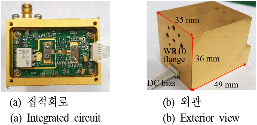
본 논문에 제시하는 fc GHz 수신기 모듈은 그림 1과 같이 저잡음 증폭기, 믹서, 스위칭 감쇠기로 구성되어 있다. 믹서를 구동하기 위한 국부발진기(LO, local oscillator)와 dc 바이어스 전압은 수신기 모듈 외부에서 공급한다. 수신기 모듈의 집적회로는 그림 2(a)와 같이 0.1 μm GaAs pHEMT 공정으로 제작되었으며, 모듈의 물리적 크기는 49 mm×35 mm×36 mm이다.
Ⅲ. 수신기 모듈의 특성측정 및 결과
제작된 수신기 모듈의 성능은 잡음특성과 IF출력 특성으로 나누어서 측정하였다.
3-1 잡음특성
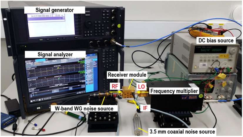
수신기 모듈은 주파수변환기인 믹서를 포함하고 있다. 믹서는 밀리미터파 입력(RF)을 국부발진기(LO)와 혼합하여 낮은 대역의 IF 출력을 내는 주파수 변환 장치이다. 이러한 주파수 변환 장치의 잡음 특성평가 방법은 문헌[6]에 상세하게 기술되어 있으며, 여기서는 측정학적으로 유의미한 부분만을 다룬다. 그림 3은 잡음특성 측정시스템을 보여준다. 먼저 측정시스템의 중심이 되는 100 GHz급 신호분석기의 잡음 측정부를 선택한다. 잡음 측정부는 2-포트 기기의 이득과 잡음지수 측정결과를 화면에 보여준다. 측정 대상 수신기 모듈의 동작 주파수는 (fc ± 0.5) GHz이다. 예를 들어 측정주파수 fc GHz이면 신호분석기의 주요 파라미터는 다음과 같이 설정한다. RF주파수 fRF= fc GHz, fLO=(fc-0.08) GHz, fIF=80 MHz, USB(upper sideband, 고 측파대).
그림 3. | Fig. 3.
수신기 모듈의 잡음특성 측정시스템 | Measurement system of noise characteristics of the receiver module.
Download Original Figure
그림 3의 측정시스템을 교정하기 위해 W-대역 도파관 잡음원과 3.5 mm 동축 잡음원을 사용하였다. W-대역 도파관 잡음원은 잡음원기시스템[7]으로 교정된 표준잡음원과 잡음원교정시스템[8]으로 교정되었다. 3.5 mm 동축 잡음원은 영국 NPL(National Physical Laboratory)에서 교정되었다. 교정값은 과도잡음비(excess noise ratio, ENR)[9]
Te=잡음원의 등가 유효(available) 잡음온도,
T0=기준온도, 290 K
로 주어진다. 잡음 측정부를 교정하기 전에 주파수별 ENR값을 신호분석기에 입력하였다. 그림 3에서 믹서의 RF입력은 W-대역 도파관 잡음원에서 발생되는 잡음이다. LO는 20 GHz 신호발생기의 출력이 주파수체배기(×6)를 통해 체배된 후 가변감쇠기로 조정되어 믹서에 공급된다. 믹서는 LSB(lower sideband, 저 측파대)에 나타나는 이미지를 저지(image rejection)하도록 설계되었으며, IF 주파수는 80 MHz이다. 그림 4는 3.5 mm 동축 잡음원으로 IF 주파수에서 시스템을 교정한 후, W-대역 도파관 잡음원을 이용한 측정시스템 구성도를 보여준다.
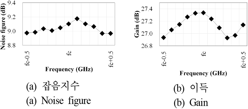
그림 5와 같이 수신기 모듈은 주파수 (fc ± 0.5) GHz 범위에서 잡음지수는 9 dB, 이득은 27 dB로 측정되었다. 유사한 기법으로 개발된 다른 수신기[4],[10]와 성능을 비교하여 표 1에 제시하였다.
표 1. | Table 1.
W-band 수신기 모듈 성능 비교 | Performance comparison of W-band receiver modules.
|
Quantities |
This work |
Reference [4]
|
Reference [10]
|
|
Technology |
0.1 μm GaAs pHEMT |
0.15 μm GaAs pHEMT |
0.1 μm GaAs pHEMT |
|
Gain (dB) |
27 |
6 |
6 |
|
Noise figure (dB) |
9 |
5 |
5 |
|
LO power (dBm) |
10 |
−1 |
NA |
|
P1dB,in (dBm) |
−11 |
−13 |
−15 |
Download Excel Table
3-2 IF 출력특성
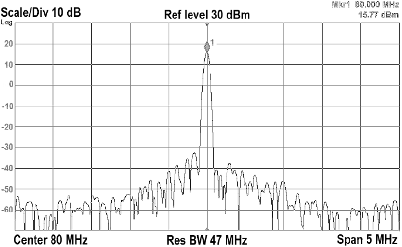
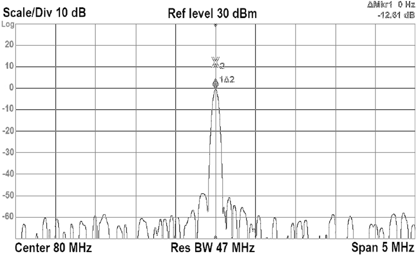
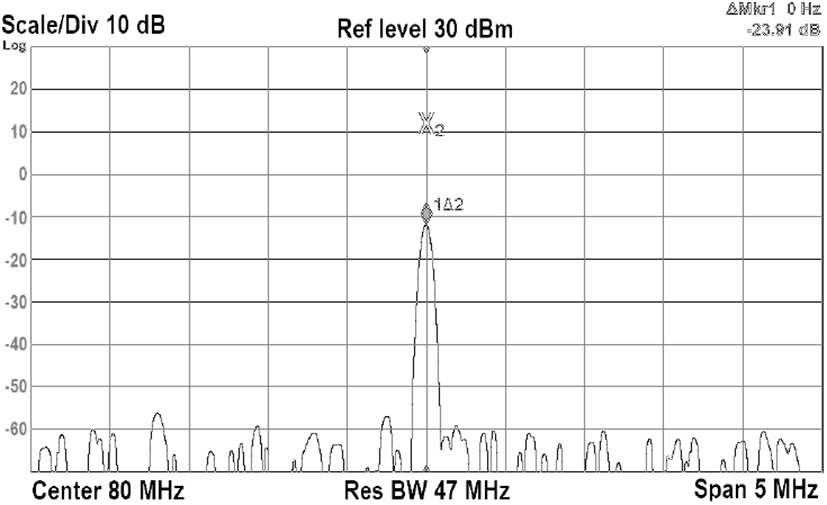
수신기 모듈은 IF 80 MHz에서 주파수 스펙트럼으로 출력된다. 신호분석기의 기본적인 스펙트럼 분석기능을 통해 출력 특성을 측정하였다. 신호분석기는 중심주파수 80 MHz, 주파수 스팬 5 MHz, 해상도 대역폭과 비디오 대역폭은 각각 47 MHz로 설정하였다. 그림 6에서 수신기모듈의 1-dB 이득 압축 IF 출력 P1dB,out이 약 16 dBm, 그림 5(b)에서 이득이 약 27 dB이므로, 대응되는 IF 입력 P1dB,in은 −11 dBm이다. 그림 7에서 이미지 저지비는 13 dB로 측정되었다. 수신기 모듈의 출력을 제어하기 위하여 스위칭 감쇠기를 수신기 모듈 내부에 내장하여 제작하고, 그 성능을 평가한 결과, 그림 8과 같이 약 24 dB의 감쇠량을 보여 설계조건에 부합되게 동작함을 확인하였다.
그림 8. | Fig. 8.
수신기 모듈에 내장된 감쇠 스위치에 의한 감쇠량 측정 | The measured attenuation of the switch embedded in the receiver module.
Download Original Figure
Ⅳ. 결 론
W-대역의 fc GHz에서 동작하는 수신기 모듈을 제작하고 성능을 평가하기 위하여 잡음특성 및 출력 특성으로 나누어서 측정하였다. 잡음특성은 표준잡음원을 사용하여 신호분석기 잡음 측정부를 교정한 후 측정하였으며, 출력 특성은 신호분석기의 기본적인 스펙트럼 분석 기능을 사용하여 측정하였다. 수신기 모듈은 주파수 fc GHz에서 잡음지수 9 dB, 이득 27 dB의 성능을 보였다. 수신기 모듈의 1-dB 이득 압축 입력전력 P1dB,in은 −11 dBm으로, IF 이미지 저지 비는 13 dB로 각각 측정되었다. 제작․평가된 수신기 모듈은 W-대역 신호탐지 시스템에 사용될 예정이다.
Acknowledgements
이 연구는 한국표준과학연구원 20011026 전자기 측정표준기술 고도화 과제 및 국방과학연구소 계약번호 UC170028FD에 의하여 지원된 과제의 연구비로 연구되었음.
References
S. Q. Xiao, M. T. Zhou, and Y. Zhang,
Millimeter Wave Technology in Wireless PAN, LAN, and MAN, New York, NY, Auerbach Publications, 2008.

H. W. Seo, J. H Park, J. S. Kim, and B. S. Kim, ℌDesign of 94-GHz high-gain differential low-noise amplifier using 65-nm CMOS,”
The Journal of Korean Institute of Electromagnetic Engineering and Science, vol. 29, no. 5, pp. 393-396, May 2018.


N. W. Moon, M. W. Lee, J. M. Jung, and Y. H. Kim, ℌDirect detection receiver for W-band radiometer,”
The Journal of Korean Institute of Electromagnetic Engineering and Science, vol. 28, no. 5, pp. 426-429, May 2017.


S. Lee, Y. Kim, S. Lee, K. Lee, W. Kim, and J. Jeong, et al., ℌW-band single-chip receiver MMIC for FMCW radar,”
Journal of the Institute of Electronics Engineers of Korea, vol. 49, no. 10, pp. 159-168, Oct. 2012.


M. Sato, H. Sato, T. Hirose, T. Ohki, T. Takahashi, and K. Makiyama, et al., ℌCompact receiver module for a 94 GHz band passive millimetre-wave imager,”
IET Microwaves, Antennas and Propagation, vol. 2, no. 8, pp. 848-853, Dec. 2008.


T. W. Kang, J. H. Kim, N. W. Kang, and J. S. Kang, ℌA thermal noise measurement system for noise temperature standards in W-band,”
IEEE Transactions on Instrumentation and Measurement,” vol. 64, no. 6, pp. 1741-1747, Jun. 2015.


T. W. Kang, J. H. Kim, J. Y. Kwon, and J. S. Kang, ℌPerformance evaluation of a W-band waveguide noise measurement system for calibrating noise sources,”
The Journal of Korean Institute of Electromagnetic Engineering and Science, vol. 24, no. 2, pp. 180-188, Feb. 2013.


R. J. Collier, A. D. Skinner,
Microwave Measurements, 3rd ed. London, The Institution of Engineering and Technology, 2007.

L. Li, Y. Gao, R. Qian, and X. Sun, ℌW-band four-channel receiver MMIC in 0.1
μm GaAs PHEMT technology,” in
2019 IEEE Asia-Pacific Microwave Conference(APMC), Singapore, Dec. 2019, pp. 1512-1514.


